版本:v1.0
摘要
本文主要介绍了RS232串口的基本知识,以及和其他众多技术的对比,包括TTL,UART,RS422,RS485等,介绍了如何进行RS232串口的开发,RS232串口在不同领域内的应用,其他不同技术和手段如何模拟串口,相关的串口工具和软件,以及常见的串口芯片。
2015-05-22
| 修订历史 | ||
|---|---|---|
| 修订 1.0 | 2015-05-22 | crl |
| ||
版权 © 2015 Crifan, http://crifan.com
目录
插图清单
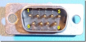
- 1.1. 公口的9针的RS232接口
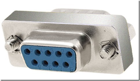
- 1.2. 母口的9针的RS232接口
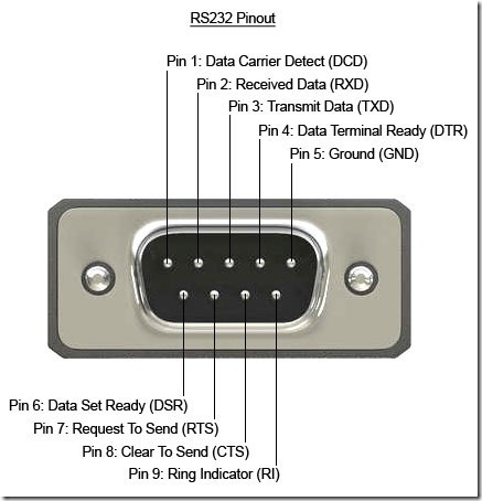
- 1.3. 公口的9针的RS232接口定义
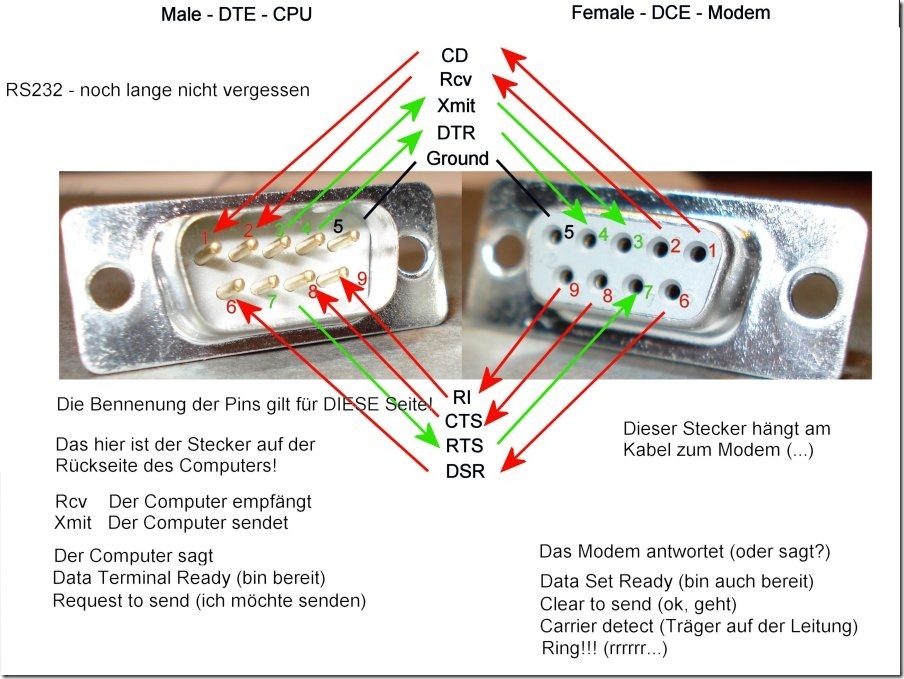
- 1.4. 9针RS232接口的公口和母口的定义和对应关系
- 1.5. 9针母口RS232接口的三个引脚
- 1.6. RS232的DCE和DTE的3线连接方式
- 1.7. RS232的时序图
- 2.1. RS232和UART之前的数据流关系
- 4.1. RS232串口接口的倍福BeckHoff的CX9000-N030
- 4.2. Beckhoff的TwinCAT的RS232子系统
表格清单
- 1.1. 9针的RS232引脚的编号定义和功能
- 2.1. Serial、RS232、UART的对比
- 2.2. RS232,RS422,RS423,RS485之间的对比
- 5.1. 蓝牙模拟串口与和标准串口的对应关系
目录
摘要
TODO:整理帖子内容
http://www.camiresearch.com/Data_Com_Basics/RS232_standard.html#anchor1155404
RS232,就是我们常说的,串口。
也常被叫做,UART。
最早的是25针的,后来有了简化版的9针的。目前最常用的就是9针的。
最早采用RS232协议的产品是调制解调器Modem和电传打字机。
RS232接口,按照引脚个数分可以分为:
- 9针=9 pins
主流最常用的就是这个9针的RS232
- 25针=25 pins
目前很少用,此处不多介绍
其中的(9针的)RS232按照接口类型分,又可分为:
此处介绍,最常用的9针的RS232的引脚的具体位置和含义。
表 1.1. 9针的RS232引脚的编号定义和功能
| RS232引脚编号 | 引脚名缩写 | 引脚名全称 | 信号传输方向 |
|---|---|---|---|
| 1 | DCD | Data Carrier Detect | <—- |
| 2 | RXD | Receive Data | <—- |
| 3 | TXD | Transmit Data | —-> |
| 4 | DTR | Data Terminal Ready | —-> |
| 5 | GND | System GRounD | —- |
| 6 | DSR | Data Set Ready | <—- |
| 7 | RTS | Request to Send | —-> |
| 8 | CTS | Clear to Send | <—- |
| 9 | RI | Ring Indicator | <—- |
对于公口的引脚的含义,图示如下:
对于公口和母口对应的关系,此图一目了然:
各个引脚的名称,功能,传输方向,以及公口和母口的位置编号
正常情况下,两个RS232接口,一个公口和母口,如前面的介绍,直接对应的插上互联就可以使用了
有时候,为了简化数据传输,仅仅使用最基本的引脚,即可实现数据传输了。
常见的有:
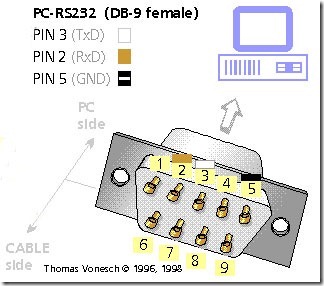
不考虑流控制(握手协议),直接数据线和接地,只用到:
- 引脚3==TxD==发送数据
- 引脚2==RxD==接受数据
- 引脚5==GND==接地
如图所示:
所以这时候,只需要连接对应的3,2,5三个引脚即可
TODO:整理
【整理】HART协议中串口配置和Handshake(RTS/CTS等)
先列出关于流控制协议的一些名词:
- DTR – Data Terminal Ready
- DSR – Data Set Ready
- RTS – Request To Send
- CTS – Clear To Send
于此相关的其他一些名词:
- DCE:Data Communication Equipment,可以理解为:数据的发起方
比如,计算机终端
- DTE:Data Terminal Equipment,可以理解为:数据的接收方
原先定义为,数据通信设备,比如调制解调器Modem
RTS/CTS和DTR/DSR,用的物理引脚是不同的;
而关于DTR/DSR和RTS/CTS共存(没有统一只使用单个的一组硬件引脚(要么用RTS/CTS,要么用DTR/DSR)去实现流控制)的原因是:
背景是:
最开始先出现的RTS/CTS,但是设计出RTS/CTS的初衷,即原先的目的,就不是把RTS/CTS去用来当做流控制的
-> 而是用来:去协调两个半双工(工作模式下的)的猫modem之间的通讯
-> 不至于让两个半双工的modem,在通讯时,互相掐架,互相抢占数据通道,互相同时要么都要发送数据,要么都要接受数据,由此而容易导致混乱和(总线上的)数据异常
-> 但是结果,(被设计用于协调两个两个半双工的modem之间的通讯的)RTS/CTS,结果被大家误用,误当做(后来大量出现和使用的,全双工的串口等设备中的)流控制
-> 即,对于都是全双工的两个串口来说:
计算机(上面的串口) <-> (开发板或其他设备上面的)串口
分别对应着的概念是:
DCE <-> DTE
此处,分别叫做:
数据发送方 <-> 数据接收方
此处,暂且叫做:
串口A <-> 串口B
此时就是:
A打算发送数据到B中
A设置RTS(Request To Send),表示:请求发送(数据到对方)
此时:
- 正常情况下,数据接收方,B不忙的时候,即不是busy的状态,则:
- B去设置对应的CTS(Clear To Send):
- 两种理解,不确定是哪种:
清除(发送者A之前的设置的RTS),表示可以接受数据了
Clear表示OK,清楚,明白,意思是明白对方的意思了,表示对方可以发送数据了
- -> 发送者A,就可以直接去发送数据给B了,B也就可以去接受数据,处理收到的数据了;
- 偶尔特殊的时候,处于忙的状态,即busy,比如忙着处理上次发送的数据呢,所以没空理会你这次还要发的数据:
- 那么此时就是:不去设置对应的CTS,表示自己忙,来不及处理你将要发送的数据
- -> 数据发送者A,见状,就继续检测CTS,直到(数据接受者B,忙清了自己手上的活,有空接受数据了,然后)CTS被接受者B去设置对应的CTS,表示可以接受数据了,然后A才去发送数据给B
DTR/DSR,主要是用来做建立链接
即,数据发送和接受之前,先要建立A和B的连接,这时候才用到DTR/DSR
A设置RTS表示要发送数据给B,而B设置CTS表示可以接受数据,通知A发送数据给B,A就开始去真正的发送数据给B了
的背景是:
硬件连接是:
- A的RTS<->B的RTS
- A的CTS<->B的CTS
对应的:
- A一般是计算机PC
- B一般是接在PC上的一个modem猫
对应的,A要发送数据给B的执行过程是:
- A设置A的RTS:表示要发数据给B;
- A检测A的CTS:
- 如果A的CTS是被设置了,那说明B设置了B的CTS
- 表示B可以接受数据了
- A就去发送数据给B了
- 表示B可以接受数据了
- 如果A的CTS没被设置,那说明B没有去设置B的CTS
- 说明B还出于busy忙的状态
- 等B忙清了,再去设置B的CTS
- 此时A才能检测到A的CTS,是被设置了,才能发送数据给B
- 等B忙清了,再去设置B的CTS
- 说明B还出于busy忙的状态
- 如果A的CTS是被设置了,那说明B设置了B的CTS
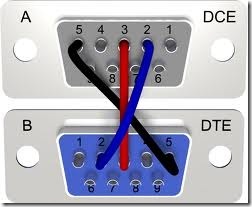
对于目前常见的,直接两个DB9的串口直接相连,物理上对应的引脚的接法:
- A的RTS,CTS,分别接B的RTS,CTS
- A的Tx,Rx,分别接B的Rx和Tx
目前对于DTR/DSR的理解:
数据发送和接受之前,先要建立A和B的连接。这时候才用到,用于建立链接的,DTR/DSR
RTS/CTS的流控制过程如下:
如果A和B,(其中A是Imager,要发送图像数据,B是对应的接受设备),A想要发送数据给B,那么用硬件的RTS/CTS作为硬件流控制机制的话,
A如果想要发送数据给B的话,A会使得RTS(Request To Send)引脚有效,表明其想要“请求发送”数据给作为接收设备的B,
然后A接着就会去检测对应的来自B的CTS引脚,直到CTS有效(此时意味着B已经做 好了相关的准备工作了,然后设置了CTS(Clear To Send) ,表明自己准备好接受数据了),才会真正开始发送数据。
并且在接下来发送每个字符(data character)之前,都会去检测对应的CTS是否有效
如果有效,才会继续传输对应的数据,
如果发现CTS无效(此时意味着B那么发生了啥情况,导 致无法继续正常接受数据了,所以将CTS设置为了无效),那么就不能再继续发送数据。
对于上述CTS一直有效的情况下,A就一直发送数据给B,到了最后数据发送完之后,再把RTS设置为无效,表示数据已经发送完了。
这就是整个单个的数据发送流程,用RTS和CTS来控制传输的逻辑。
对此流程,做个简单的比喻,未必很恰当,但是可以很形象的说明数据发送的流程:
A和B,相当于马路的两边,A要发送数据给B,就相当于A要过马路,具体的流程就是:
- A说,我要过马路
就相当于A要将CTS设置有效,表示要发送数据(过马路到B那里去)
- B根据自己情况,决定亮红灯不允许过,还是亮绿灯允许过(CTS有效)
B对于接下来将要接受的数据,要有一个准备的过程,这要花点时间,在这段时间内,肯定不会让你发送数据
也就是亮红灯不允许你过马路,将CTS设置无效,表示我还没准备好
然后A那边呢就一直检测CTS是否有效,发现是无效,就知道现在B那边还没准备好,不允许我发送数据
然后过了会B准备好了, 就把CTS设置为有效,表示准备好了,A可以发送数据给B了,即亮绿灯,让A过马路了
而A此时就检测到CTS是有效的了,就可以发送数据了,即看到绿灯,可以过马路了。
- A要发送给B的每一个字节数据之前,都会看看是否是绿灯,如果是,继续发送数据,如果不是,就停止发送
接下来的,A要把一个个字节的数据(就相当于一个个要过马路的人),发送给B
在发送之前都要像前面一样,去检测CTS是否有效
如果有效,就亮绿灯,可以继续发送数据,即过马路
如果CTS无效,说明B出啥问题了,比如缓存满了,要处理一下,接着再让你发送数据,就亮红灯,A不能继续过马路了。
然后A就一直检测CTS直到CTS有效,再发送数据,即A一直看灯,直到红灯变绿,再继续过马路。
- 在CTS一直有效的情况下,A发送数据完成后,把RTS设置为无效
所有的A都过完马路了,就把原先设置的标示RTS设置为无效,表示数据发送完成了。
可以将上面一大堆繁琐的解释,总结为简单的逻辑:
- A先设置RTS为1,表示要发数据给B
- B检测到了RTS为1,就看看自己是否已经准备好: <listitem>如果准备好,就设置CTS为1表示A可以发送数据给我B了;</listitem><listitem>如果没有准备好,那就继续处理需要处理的事情,比如缓存满了,尽快去搬移数据。弄完了,再去设置CTS为1,让A发送数据过来。</listitem>
- A发现CTS为1了,就开发发送数据给B。
- A每发送一次数据给B之前,都继续上面的逻辑,就是先检测CTS是否为1,如果不是1,继续等待,如果是1,就发送数据。
- A把所有数据都发送完毕了,就去设置为RTS为0,表示数据发送完了。B也就不会再去准备接受数据了。
RS-232 - A standard defining the signals between two devices, defining the signal names, their purpose, voltage levels, connectors and pinouts. This is a specific interface standard that allows for equipment interoperability. While two pieces of hardware may have UARTs, you don't know that they'll connect without damage, or communicate properly unless you know they have the same pinout and voltage standards, or include a converter or specially wired cable specific to the interconnection of these two specificl devices. To avoid the need for special converters or cables, the manufacturers may choose to follow the RS-232 standard. You know, then, that a standard RS-232 cable will connect the two. However, neither the UART, nor the RS-232 standard define what is sent on the TX and RX lines. Generally, when people use RS-232, they use a simple 8 bit NRZ encoding with one start bit and one stop bit. Most equipment today manufactured uses this encoding, but there's no requirement to do so. You can find older equipment that includes parity bits, or uses 7 or 9 bits. The UART can be configured to support these various protocols on its TX and RX lines. UARTs do not typically interface directly with RS-232. You will need to convert the output of the UART to the +/-12V standard that RS-232 requires. A complete RS-232 interface will typically involve both a UART and an RS-232 level converter. Further, the RS-232 standard includes the definition of several other signalling pins besides TX and RX, which you may need to use depending on the equipment you need to connect to. These will also need to be level converted, and your UART may, or may not, support these signals. If it does not you will have to control them with your software/firmware directly. So while a UART may help you implement an RS-232 interface, it is not an RS-232 interface itself.
目录
摘要
此处介绍,和RS232类似的,常被那来作对比的一些协议和接口,详细解释他们之间的区别和联系:
RS232:只能一对一的连接
RS485:支持一对多的连接,即一拖多
RS232:各种领域,包括普通消费类,工业控制类等等都有广泛应用
RS485:相对来说更多的是应用于工业控制领域内
其实RS232和UART不是一个东西,是有区别的。下面就来解释RS232和UART的关系。
只不过在多数情况下,都把UART和RS232混在一起说,此时都是指的是串口的意思
UART==Universal Asynchronous Receiver Transmitter
UART,通用,指的是:其可以配置而支持多种不同协议
即,UART的输出是很多bit,这些bit最终可以组成RS232、RS422、RS485等其他协议。
The UART (universal asynchronous receiver transmitter) is the heart of the serial hardware. It is a chip or part of a chip with the purpose to convert between parallel data and serial data. RS-232 UARTs also typically add the necessary start/stop and parity bits when transmitting, and decode this information when receiving.
A UART typically operates entirely on computer logic voltage. Its serial data input/output voltage is the computer logic voltage, not the serial line voltage. They leave the actual line interface to a particular line driver / receiver. This line driver / receiver does not necessarily need to be an RS-232 line driver / receiver, but could e.g. also be an RS-422 differential driver / receiver. This, and the fact that baud rate, parity, number of stop bits, number of data bits are programmable is the reason why UARTs are called universal. The distinction between UART and line driver / receiver blurs if they are both placed in the same chip. Such chips are typically also sold under the label 'UART'. UARTs are called asynchronous, because they don't use a special clock signal to synchronize with the the remote side. Instead, they use the start/stop bits to identify the data bits in the serial stream. Thanks to the UART the rest of the hardware, as well as the software application can deal with normal bytes to hold the communication data. It is the job of the UART to chop a byte into a series of serial bits when sending, and to assemble series of bits into a byte when receiving. UARTs typically contain eight bit wide receiver and transmission buffers. Of which not all bits might be used if e.g. a 7 bit transmission is used. Received serial data is provided in parallel in the receiver buffer, to-be-send data is written in parallel to the transmission buffer. Depending on the UART the buffers might just have a depth of one byte, or a few bytes (in the range of 15 or 16 bytes). The less deep the buffers are, the more precise the communication with the CPU needs to be. E.g. if the receiver buffer just has a depth of one byte, and the data is not fetched fast enough, the next received data can overwrite the previously received data in the buffer, and the previously received data is lost.
Because of the fact that the timing on the serial interface is important, UARTs are typically connected to a baud rate generator, either an internal one in the UART chip, or an external one.
UART的作用:
为了CPU更省事,省力:
不需要每次把一堆的字节,慢慢的转化为一个个bit,然后一点点塞到(设置到)传输通道中,发送到对方
而只需要:
把要发的数据字节流放到一个缓存buffer中,然后告诉UART有数据了,接着UART负责把每个字节转换为单个的8个bit,一点点去发送
简单说就是:
UART是把串行的字节数据,转换为并行的比特位,然后再传输过去
总结起来就是:
表 2.1. Serial、RS232、UART的对比
| 要对比的项 | 所属类型 | 数据位个数 | 主要作用和功能 | 备注 |
|---|---|---|---|---|
| Serial | 软件概念 | 串行,概念上属于“时分复用”,数据是随着时间不同,慢慢的传送过去的,且大多数是以一个一个bit位的形式发送的。USART, UART, RS232, USB, SPI, I2C, TTL等等,都属于串行方面的协议或概念。 | ||
| UART | 硬件设备,电子电路,物理上的模块 | 1 | 最常用的一种串行协议。处理串行接口之间的通信,只不过此串行接口,往往都是RS232接口而已。 | 由于每传输一个字节,都要通过自己的起始位的下降沿起去同步,因此才叫做异步通信。 |
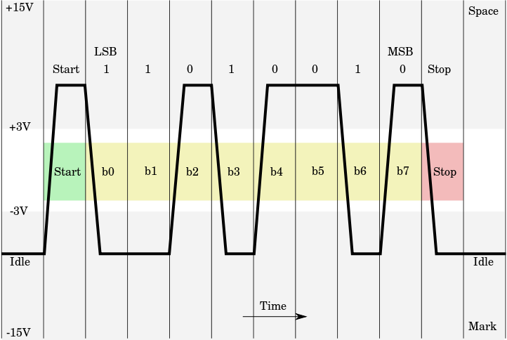
| RS232 | 电气接口规范 | 2 | 串口通信的协议,定义了,DCE和DTE之间的,电气方面的特性:硬件接口即引脚和其功能,信号时序和含义等 | 更严格的说法应该把RS232叫做EIA-232;对于远距离通信,5V不可靠,所以才会加大电压采用12V,即+12V表示0,-12V表示1 |
RS232和UART,以及对应的Line Driver/Receiver,CPU等等模块之间的数据流关系,可用下图表示:
TODO:整理帖子内容
TTL (Transistor Transistor Logic) is not a protocol. It's an older technology for digital logic, but the name is often used to refer to the 5 V supply voltage, often incorrectly referring to what should be called UART.
TTL mean Transistor-Transistor-Logic and has its level for logical zero near 0V and for logical one near 5V. Often any 5V logic is called TTL, although most circuits nowadays are built as CMOS. Today there are also many circuits that work at 3.3V, which is no longer TTL.
表 2.2. RS232,RS422,RS423,RS485之间的对比
| RS232 | RS422 | RS423 | RS485 | |
|---|---|---|---|---|
| Differential | no | yes | no | yes |
| Max number of drivers | 1 | 1 | 1 | 32 |
| Max number of receivers | 1 | 10 | 10 | 32 |
| Modes of operation | half duplex, full duplex | half duplex | half duplex | half duplex |
| Network topology | point-to-point | multidrop | multidrop | multidrop |
| Max distance (acc. standard) | 15 m | 1200 m | 1200 m | 1200 m |
| Max speed at 12 m | 20 kbs | 10 Mbs | 100 kbs | 35 Mbs |
| Max speed at 1200 m | (1 kbs) | 100 kbs | 1 kbs | 100 kbs |
| Max slew rate | 30 V/μs | n/a | adjustable | n/a |
| Receiver input resistance | 3~7 kΩ | ≧ 4 kΩ | ≧ 4 kΩ | ≧ 12 kΩ |
| Driver load impedance | 3~7 kΩ | 100 Ω | ≧ 450 Ω | 54 Ω |
| Receiver input sensitivity | ±3 V | ±200 mV | ±200 mV | ±200 mV |
| Receiver input range | ±15 V | ±10 V | ±12 V | –7~12 V |
| Max driver output voltage | ±25 V | ±6 V | ±6 V | –7~12 V |
| Min driver output voltage (with load) | ±5 V | ±2.0 V | ±3.6 V | ±1.5 V |
嵌入式领域,尤其是其中的消费类数码领域的嵌入式开发,往往都会将这几种常见的接口,放在一起讨论。
所以,此处也在简单对比分析一下,RS232和SPI,I2C等接口的区别。
SPI (Serial Peripheral Interface) is another very simple serial protocol. A master sends a clock signal, and upon each clock pulse it shifts one bit out to the slave, and one bit in, coming from the slave. Signal names are therefore SCK for clock, MOSI for Master Out Slave In, and MISO for Master In Slave Out. By using SS (Slave Select) signals the master can control more than 1 slave on the bus. There are two ways to connect multiple slave devices to one master, one is mentioned above i.e. using slave select, and other is daisy chaining, it uses less hardware pins(select lines), but software gets complicated.
I2C (Inter-Integrated Circuit, pronounced "I squared C") is also a synchronous protocol, and it's the first we see which has some "intelligence" in it; the other ones dumbly shifted bits in and out, and that was that. I2C uses only 2 wires, one for the clock (SCL) and one for the data (SDA). That means that master and slave send data over the same wire, again controlled by the master who creates the clock signal. I2C doesn't use separate Slave Selects to select a particular device, but has addressing. The first byte sent by the master holds a 7 bit address (so that you can use 127 devices on the bus) and a read/write bit, indicating whether the next byte(s) will also come from the master of should come from the slave. After each byte receiver must send a "0" to acknowledge the reception of the byte, which the master latches with a 9th clock pulse. If the master wants to write a byte the same process repeats: the master puts bit after bit on the bus and each time gives a clock pulse to signal that the data is ready to be read. If the master wants to receive data it only generates the clock pulses. The slave has to take care that the next bit is ready when the clock pulse is given. This protocol is patented by NXP(formerly Phillips), to save licensing cost, Atmel using the word TWI(2-wire interface) which exactly same as I2C, so any AVR device will not have I2C but it will have TWI. Two or more signals on the same wire may cause conflicts, and you would have a problem if one device sends a "1" while the other sends a "0". Therefore the bus is wired-OR'd: two resistors pull the bus to a high level, and the devices only send low levels. If they want to send a high level they simply release the bus.
摘要
TODO:
摘要
PLC中,外(部挂)接其他设备支持各种接口,其中就包括最常用的RS232串口。
比如,IndraLogic的PLC组态期间,除了常见的其他总线,比如Profibus,CAN等等,还可以设置RS232的支持。
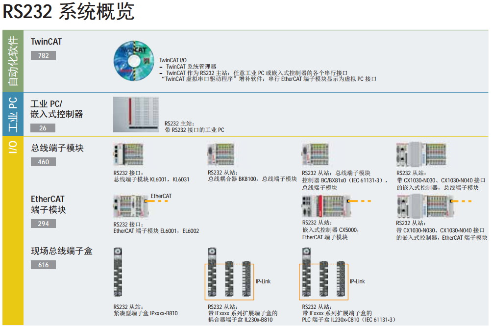
其他现场总线方面的产品,比如还有,串口RS232模块KL6001,以及RS232串口的Beckhoff的CX9000-N030:
另外,比如Beckhoff倍福的很多工控模块和协议中,也有RS232的支持。比如TwinCAT系统中就有对于RS232的支持:
RS232,作为嵌入式开发和调试的工具和手段,是使用最为普遍的。
即,嵌入式开发中的固件烧录方式,除了通过其他手段,比如SD、USB等方式进行烧录之外,还可以通过RS232去将程序通过串口下载到目标开发板(中的RAM中)。
摘要
由于RS232串口的应用极其广泛,所以在很多其他技术领域内,往往也是为了兼容已有的RS232串口通信,而去用其他技术或手段去模拟出RS232串口。
下面就来总结一下,有哪些模拟RS232串口的技术和手段:
摘要
此处整理和RS232串口方面的各种软件和工具:
TODO:
Windows系统,比如WinXP,默认已自带串口工具:超级终端。
而Win7中,不自带了,需要自己额外下载:
TODO:整理帖子 【整理】RS232 RTS/CTS的流控制的具体过程/机制 | 在路上
[7] Elektronik
[9] RTS/CTS
[14] RS232串口通信基本接线方法
[15] RS-232接线
[16] RS232 Data Interface
[18] The RS232 STANDARD
![[提示]](http://www.crifan.com/files/res/docbook/images/tip.png)
