What is 802.11 & 802.11B ?
http://www.pulsewan.com/data101/802_11_b_basics.htm
What?s New in Wireless LANs: The IEEE 802.11b Standard
A wireless LAN (WLAN) is a data transmission system designed to provide location-independent network access between computing devices by using radio waves rather than a cable infrastructure. In the corporate enterprise, wireless LANs are usually implemented as the final link between the existing wired network and a group of client computers, giving these users wireless access to the full resources and services of the corporate network across a building or campus setting.
WLANs are on the verge of becoming a mainstream connectivity solution for a broad range of business customers. The wireless market is expanding rapidly as businesses discover the productivity benefits of going wire-free. According to Frost and Sullivan, the wireless LAN industry exceeded $300 million in 1998 and will grow to $1.6 billion in 2005. To date, wireless LANs have been primarily implemented in vertical applications such as manufacturing facilities, warehouses, and retail stores. The majority of future wireless LAN growth is expected in healthcare facilities, educational institutions, and corporate enterprise office spaces. In the corporation, conference rooms, public areas, and branch offices are likely venues for WLANs.
The widespread acceptance of WLANs depends on industry standardization to ensure product compatibility and reliability among the various manufacturers. The Institute of Electrical and Electronics Engineers (IEEE) ratified the original 802.11 specification in 1997 as the standard for wireless LANs. That version of 802.11 provides for 1 Mbps and 2 Mbps data rates and a set of fundamental signaling methods and other services.
The most critical issue affecting WLAN demand has been limited throughput. The data rates supported by the original 802.11 standard are too slow to support most general business requirements and have slowed adoption of WLANs. Recognizing the critical need to support higher data-transmission rates, the IEEE recently ratified the 802.11b standard (also known as 802.11 High Rate) for transmissions of up to 11 Mbps. Global regulatory bodies and vendor alliances have endorsed this new high-rate standard, which promises to open new markets for WLANs in large enterprise, small office, and home environments. With 802.11b, WLANs will be able to achieve wireless performance and throughput comparable to wired Ethernet.
Outside of the standards bodies, wireless industry leaders have united to form the Wireless Ethernet Compatibility Alliance (WECA). WECA’s mission is to certify cross-vendor interoperability and compatibility of IEEE 802.11b wireless networking products and to promote that standard for the enterprise, the small business, and the home. Members include WLAN semiconductor manufacturers, WLAN providers, computer system vendors, and software makers?such as 3Com, Aironet, Apple, Breezecom, Cabletron, Compaq, Dell, Fujitsu, IBM, Intersil, Lucent Technologies, No Wires Needed, Nokia, Samsung, Symbol Technologies, Wayport, and Zoom.
The Competitive Advantage of Going Wireless
Today?s business environment is characterized by an increasingly mobile workforce and flatter organizations. Employees are equipped with notebook computers and spend more of their time working in teams that cross functional, organizational, and geographic boundaries. Much of these workers? productivity occurs in meetings and away from their desks. Users need access to the network far beyond their personal desktops. WLANs fit well in this work environment, giving mobile workers much-needed freedom in their network access. With a wireless network, workers can access information from anywhere in the corporation?a conference room, the cafeteria, or a remote branch office. Wireless LANs provide a benefit for IT managers as well, allowing them to design, deploy, and enhance networks without regard to the availability of wiring, saving both effort and dollars.
Businesses of all sizes can benefit from deploying a WLAN system, which provides a powerful combination of wired network throughput, mobile access, and configuration flexibility. The economic benefits can add up to as much as $16,000 per user?measured in worker productivity, organizational efficiency, revenue gain, and cost savings?over wired alternatives.1 Specifically, WLAN advantages include:
- Mobility that improves productivity with real-time access to information, regardless of worker location, for faster and more efficient decision making
- Cost-effective network setup for hard-to-wire locations such as older buildings and solid-wall structures
- Reduced cost of ownership?particularly in dynamic environments requiring frequent modifications?thanks to minimal wiring and installation costs per device and user
WLANs liberate users from dependence on hard-wired access to the network backbone, giving them anytime, anywhere network access. This freedom to roam offers numerous user benefits for a variety of work environments, such as:
- Immediate bedside access to patient information for doctors and hospital staff
- Easy, real-time network access for on-site consultants or auditors
- Improved database access for roving supervisors such as production line managers, warehouse auditors, or construction engineers
- Simplified network configuration with minimal MIS involvement for temporary setups such as trade shows or conference rooms
- Faster access to customer information for service vendors and retailers, resulting in better service and improved customer satisfaction
- Location-independent access for network administrators, for easier on-site troubleshooting and support
- Real-time access to study group meetings and research links for students
1 ?Wireless Local Area Networking: ROI/Cost-Benefit Study,? WLANA, October 1998.
IEEE 802.11 and 802.11b Technology
As the globally recognized LAN authority, the IEEE 802 committee has established the standards that have driven the LAN industry for the past two decades, including 802.3 Ethernet, 802.5 Token Ring, and 802.3z 100BASE-T Fast Ethernet. In 1997, after seven years of work, the IEEE published 802.11, the first internationally sanctioned standard for wireless LANs. In September 1999 they ratified the 802.11b ?High Rate? amendment to the standard, which added two higher speeds (5.5 and 11 Mbps) to 802.11.
With 802.11b WLANs, mobile users can get Ethernet levels of performance, throughput, and availability. The standards-based technology allows administrators to build networks that seamlessly combine more than one LAN technology to best fit their business and user needs.
Like all IEEE 802 standards, the 802.11 standards focus on the bottom two levels of the ISO model, the physical layer and data link layer (Figure 1 on page 4). Any LAN application, network operating system, or protocol, including TCP/IP and Novell NetWare, will run on an 802.11-compliant WLAN as easily as they run over Ethernet.
The basic architecture, features, and services of 802.11b are defined by the original 802.11 standard. The 802.11b specification affects only the physical layer, adding higher data rates and more robust connectivity.
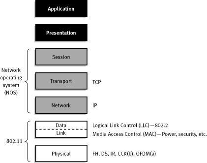
Figure 1. 802.11 and the ISO Model
802.11 Operating Modes
802.11 defines two pieces of equipment, a wireless station, which is usually a PC equipped with a wireless network interface card (NIC), and an access point (AP), which acts as a bridge between the wireless and wired networks. An access point usually consists of a radio, a wired network interface (e.g., 802.3), and bridging software conforming to the 802.1d bridging standard. The access point acts as the base station for the wireless network, aggregating access for multiple wireless stations onto the wired network. Wireless end stations can be 802.11 PC Card, PCI, or ISA NICs, or embedded solutions in non-PC clients (such as an 802.11-based telephone handset).
The 802.11 standard defines two modes: infrastructure mode and ad hoc mode. In infrastructure mode (Figure 2), the wireless network consists of at least one access point connected to the wired network infrastructure and a set of wireless end stations. This configuration is called a Basic Service Set (BSS). An Extended Service Set (ESS) is a set of two or more BSSs forming a single subnetwork. Since most corporate WLANs require access to the wired LAN for services (file servers, printers, Internet links) they will operate in infrastructure mode.
Ad hoc mode (also called peer-to-peer mode or an Independent Basic Service Set, or IBSS) is simply a set of 802.11 wireless stations that communicate directly with one another without using an access point or any connection to a wired network (Figure 3). This mode is useful for quickly and easily setting up a wireless network anywhere that a wireless infrastructure does not exist or is not required for services, such as a hotel room, convention center, or airport, or where access to the wired network is barred (such as for consultants at a client site).
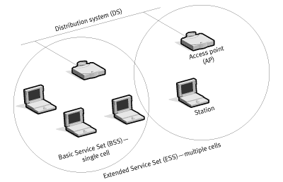
Figure 2. Infrastructure Mode
The 802.11 Physical Layer
The three physical layers originally defined in 802.11 included two spread-spectrum radio techniques and a diffuse infrared specification. The radio-based standards operate within the 2.4 GHz ISM band. These frequency bands are recognized by international regulatory agencies, such as the FCC (USA), ETSI (Europe), and the MKK (Japan) for unlicensed radio operations. As such, 802.11-based products do not require user licensing or special training. Spread-spectrum techniques, in addition to satisfying regulatory requirements, increase reliability, boost throughput, and allow many unrelated products to share the spectrum without explicit cooperation and with minimal interference.
The original 802.11 wireless standard defines data rates of 1 Mbps and 2 Mbps via radio waves using frequency hopping spread spectrum (FHSS) or direct sequence spread spectrum (DSSS). It is important to note that FHSS and DSSS are fundamentally different signaling mechanisms and will not interoperate with one another.
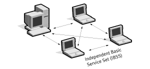
Figure 3. Ad Hoc Mode
Using the frequency hopping technique, the 2.4 GHz band is divided into 75 one-MHz subchannels. The sender and receiver agree on a hopping pattern, and data is sent over a sequence of the subchannels. Each conversation within the 802.11 network occurs over a different hopping pattern, and the patterns are designed to minimize the chance of two senders using the same subchannel simultaneously.
FHSS techniques allow for a relatively simple radio design, but are limited to speeds of no higher than 2 Mbps. This limitation is driven primarily by FCC regulations that restrict subchannel bandwidth to 1 MHz. These regulations force FHSS systems to spread their usage across the entire 2.4 GHz band, meaning they must hop often, which leads to a high amount of hopping overhead.
In contrast, the direct sequence signaling technique divides the 2.4 GHz band into 14 twenty-two MHz channels. Adjacent channels overlap one another partially, with 3 of the 14 being completely nonoverlapping. Data is sent across one of these 22 MHz channels without hopping to other channels. To compensate for noise on a given channel, a technique called ?chipping? is used. Each bit of user data is converted into a series of redundant bit patterns called ?chips.? The inherent redundancy of each chip combined with spreading the signal across the 22 MHz channel provides for a form of error checking and correction; even if part of the signal is damaged, it can still be recovered in many cases, minimizing the need for retransmissions.
802.11b Enhancements to the PHY Layer
The key contribution of the 802.11b addition to the wireless LAN standard was to standardize the physical layer support of two new speeds, 5.5 Mbps and 11 Mbps. To accomplish this, DSSS had to be selected as the sole physical layer technique for the standard since, as noted above, frequency hopping cannot support the higher speeds without violating current FCC regulations. The implication is that 802.11b systems will interoperate with 1 Mbps and 2 Mbps 802.11 DSSS systems, but will not work with 1 Mbps and 2 Mbps 802.11 FHSS systems.
The original 802.11 DSSS standard specifies an 11-bit chipping?called a Barker sequence?to encode all data sent over the air. Each 11-chip sequence represents a single data bit (1 or 0), and is converted to a waveform, called a symbol, that can be sent over the air. These symbols are transmitted at a 1 MSps (1 million symbols per second) symbol rate using a technique called Binary Phase Shift Keying (BPSK). In the case of 2 Mbps, a more sophisticated implementation called Quadrature Phase Shift Keying (QPSK) is used; it doubles the data rate available in BPSK, via improved efficiency in the use of the radio bandwidth.
To increase the data rate in the 802.11b standard, advanced coding techniques are employed. Rather than the two 11-bit Barker sequences, 802.11b specifies Complementary Code Keying (CCK), which consists of a set of 64 eight-bit code words. As a set, these code words have unique mathematical properties that allow them to be correctly distinguished from one another by a receiver even in the presence of substantial noise and multipath interference (e.g., interference caused by receiving multiple radio reflections within a building). The 5.5 Mbps rate uses CCK to encode 4 bits per carrier, while the 11 Mbps rate encodes 8 bits per carrier. Both speeds use QPSK as the modulation technique and signal at 1.375 MSps. This is how the higher data rates are obtained. Table 1 shows the differences.
| Table 1. 802.11b Data Rate Specifications | ||||
| Data Rate | Code Length | Modulation | Symbol Rate | Bits/Symbol |
|---|---|---|---|---|
| 1 Mbps | 11 (Barker Sequence) | BPSK | 1 MSps | 1 |
| 2 Mbps | 11 (Barker Sequence) | QPSK | 1 MSps | 2 |
| 5.5 Mbps | 8 (CCK) | QPSK | 1.375 MSps | 4 |
| 11 Mbps | 8 (CCK) | QPSK | 1.375 MSps | 8 |
To support very noisy environments as well as extended range, 802.11b WLANs use dynamic rate shifting, allowing data rates to be automatically adjusted to compensate for the changing nature of the radio channel. Ideally, users connect at the full 11 Mbps rate. However when devices move beyond the optimal range for 11 Mbps operation, or if substantial interference is present, 802.11b devices will transmit at lower speeds, falling back to 5.5, 2, and 1 Mbps. Likewise, if the device moves back within the range of a higher-speed transmission, the connection will automatically speed up again. Rate shifting is a physical-layer mechanism transparent to the user and the upper layers of the protocol stack.
The 802.11 Data Link Layer
The data link layer within 802.11 consists of two sublayers: Logical Link Control (LLC) and Media Access Control (MAC). 802.11 uses the same 802.2 LLC and 48-bit addressing as other 802 LANs, allowing for very simple bridging from wireless to IEEE wired networks, but the MAC is unique to WLANs.
The 802.11 MAC is very similar in concept to 802.3, in that it is designed to support multiple users on a shared medium by having the sender sense the medium before accessing it. For 802.3 Ethernet LANs, the Carrier Sense Multiple Access with Collision Detection (CSMA/CD) protocol regulates how Ethernet stations establish access to the wire and how they detect and handle collisions that occur when two or more devices try to simultaneously communicate over the LAN. In an 802.11 WLAN, collision detection is not possible due to what is known as the ?near/far? problem: to detect a collision, a station must be able to transmit and listen at the same time, but in radio systems the transmission drowns out the ability of the station to ?hear? a collision.
To account for this difference, 802.11 uses a slightly modified protocol known as Carrier Sense Multiple Access with Collision Avoidance (CSMA/CA) or the Distributed Coordination Function (DCF). CSMA/CA attempts to avoid collisions by using explicit packet acknowledgment (ACK), which means an ACK packet is sent by the receiving station to confirm that the data packet arrived intact.
CSMA/CA works as follows. A station wishing to transmit senses the air, and, if no activity is detected, the station waits an additional, randomly selected period of time and then transmits if the medium is still free. If the packet is received intact, the receiving station issues an ACK frame that, once successfully received by the sender, completes the process. If the ACK frame is not detected by the sending station, either because the original data packet was not received intact or the ACK was not received intact, a collision is assumed to have occurred and the data packet is transmitted again after waiting another random amount of time.
CSMA/CA thus provides a way of sharing access over the air. This explicit ACK mechanism also handles interference and other radio-related problems very effectively. However, it does add some overhead to 802.11 that 802.3 does not have, so that an 802.11 LAN will always have slower performance than an equivalent Ethernet LAN.
Another MAC-layer problem specific to wireless is the ?hidden node? issue, in which two stations on opposite sides of an access point can both ?hear? activity from an access point, but not from each other, usually due to distance or an obstruction. To solve this problem, 802.11 specifies an optional Request to Send/Clear to Send (RTS/CTS) protocol at the MAC layer. When this feature is in use, a sending station transmits an RTS and waits for the access point to reply with a CTS. Since all stations in the network can hear the access point, the CTS causes them to delay any intended transmissions, allowing the sending station to transmit and receive a packet acknowledgment without any chance of collision. Since RTS/CTS adds additional overhead to the network by temporarily reserving the medium, it is typically used only on the largest-sized packets, for which retransmission would be expensive from a bandwidth standpoint.
Finally, the 802.11 MAC layer provides for two other robustness features: CRC checksum and packet fragmentation. Each packet has a CRC checksum calculated and attached to ensure that the data was not corrupted in transit. This is different from Ethernet, where higher-level protocols such as TCP handle error checking. Packet fragmentation allows large packets to be broken into smaller units when sent over the air, which is useful in very congested environments or when interference is a factor, since larger packets have a better chance of being corrupted. This technique reduces the need for retransmission in many cases and thus improves overall wireless network performance. The MAC layer is responsible for reassembling fragments received, rendering the process transparent to higher-level protocols.
Association, Cellular Architectures, and Roaming
The 802.11 MAC layer is responsible for how a client associates with an access point. When an 802.11 client enters the range of one or more APs, it chooses an access point to associate with (also called joining a Basic Service Set), based on signal strength and observed packet error rates. Once accepted by the access point, the client tunes to the radio channel to which the access point is set. Periodically it surveys all 802.11 channels in order to assess whether a different access point would provide it with better performance characteristics. If it determines that this is the case, it reassociates with the new access point, tuning to the radio channel to which that access point is set (Figure 4).
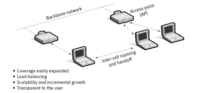
Figure 4. Access Point Roaming
Reassociation usually occurs because the wireless station has physically moved away from the original access point, causing the signal to weaken. In other cases, reassociation occurs due to a change in radio characteristics in the building, or due simply to high network traffic on the original access point. In the latter case this function is known as ?load balancing,? since its primary function is to distribute the total WLAN load most efficiently across the available wireless infrastructure.
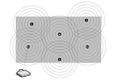
Figure 5. Unlimited Roaming
This process of dynamically associating and reassociating with APs allows network managers to set up WLANs with very broad coverage by creating a series of overlapping 802.11b cells throughout a building or across a campus. To be successful, the IT manager ideally will employ ?channel reuse,? taking care to set up each access point on an 802.11 DSSS channel that does not overlap with a channel used by a neighboring access point (Figure 5). As noted above, while there are 14 partially overlapping channels specified in 802.11 DSSS, there are only three channels that do not overlap at all, and these are the best to use for multicell coverage. If two APs are in range of one another and are set to the same or partially overlapping channels, they may cause some interference for one another, thus lowering the total available bandwidth in the area of overlap.
Support for Time-Bounded Data
Time-bounded data such as voice and video is supported in the 802.11 MAC specification through the Point Coordination Function (PCF). As opposed to the DCF, where control is distributed to all stations, in PCF mode a single access point controls access to the media. If a BSS is set up with PCF enabled, time is spliced between the system being in PCF mode and in DCF (CSMA/CA) mode. During the periods when the system is in PCF mode, the access point will poll each station for data, and after a given time move on to the next station. No station is allowed to transmit unless it is polled, and stations receive data from the access point only when they are polled. Since PCF gives every station a turn to transmit in a predetermined fashion, a maximum latency is guaranteed. A downside to PCF is that it is not particularly scalable, in that a single point needs to have control of media access and must poll all stations, which can be ineffective in large networks.
Power Management
In addition to controlling media access, the 802.11 HR MAC supports power conservation to extend the battery life of portable devices. The standard supports two power-utilization modes, called Continuous Aware Mode and Power Save Polling Mode. In the former, the radio is always on and drawing power, whereas in the latter, the radio is ?dozing,? with the access point queuing any data for it. The client radio will wake up periodically in time to receive regular beacon signals from the access point. The beacon includes information regarding which stations have traffic waiting for them, and the client can thus awake upon beacon notification and receive its data, returning to sleep afterward.
Security
802.11 provides for both MAC layer (OSI Layer 2) access control and encryption mechanisms, which are known as Wired Equivalent Privacy (WEP), with the objective of providing wireless LANs with security equivalent to their wired counterparts. For the access control, the ESSID (also known as a WLAN Service Area ID) is programmed into each access point and is required knowledge in order for a wireless client to associate with an access point. In addition, there is provision for a table of MAC addresses called an Access Control List to be included in the access point, restricting access to clients whose MAC addresses are on the list.
For data encryption, the standard provides for optional encryption using a 40-bit shared-key RC4 PRNG algorithm from RSA Data Security. All data sent and received while the end station and access point are associated can be encrypted using this key. In addition, when encryption is in use, the access point will issue an encrypted challenge packet to any client attempting to associate with it. The client must use its key to encrypt the correct response in order to authenticate itself and gain network access.
Beyond Layer 2, 802.11 HR WLANs support the same security standards supported by other 802 LANs for access control (such as network operating system logins) and encryption (such as IPSec or application-level encryption). These higher-layer technologies can be used to create end-to-end secure networks encompassing both wired LAN and WLAN components, with the wireless piece of the network gaining unique additional security from the 802.11 feature set.
Considerations for Choosing a Wireless LAN
While the bulk of this paper has described how 802.11b wireless LANs are alike, there are still many ways for wireless LAN vendors to differentiate themselves in the marketplace that will affect a customer?s purchasing decision. We cover some of these areas below.
Ease of Setup
To install a wireless LAN one must install and configure APs and PC Cards. The most important piece of this effort is proper placement of the APs. Access point placement is what ensures the coverage and performance required by the network design. There are several features that provide assistance in the installation process:
- Site survey. For complete wireless LANs employing a cellular architecture, proper placement of APs is best determined by performing a site survey, in which the person installing the WLAN can place APs and record signal strength and quality information while moving about the intended coverage area. While most vendors provide a site survey tool, these utilities vary in the amount and quality of information they provide, as well as in their logging and reporting capabilities.
- Power over Ethernet. Some vendors ship APs that can be powered over the Ethernet cable that connects the access point to the wired network. This is usually implemented by a piece of equipment in the wiring closet that takes in AC power and the data connection from the wired switch, and then outputs DC power over unused wire pairs in the networking cable that runs between the module and the access point. This feature eliminates the need to run an AC power cable out to the access point (usually located on the wall or ceiling), making installation quicker and more affordable.
- Easy-to-use NIC and access point configuration tools. Once the APs are installed, both APs and NICs must be configured for use. As with any technical product, the quality of the user interface determines the amount of time required to configure the network for operation. In addition, some vendors supply tools for bulk configuration of access points on the same network, greatly easing network setup. Finally, having a variety of methods to access the access point is helpful to ensure simple setup. Configuration options include telnet; Web-based; or SNMP-based over the Ethernet cable, from a wireless station, or via a serial port built into the access point.
Ease of Management
Since an 802.11 wireless LAN differs from standard 802.3 and 802.5 wired LANs only at OSI Layers 1 and 2, one should expect at least the same level of manageability from these products as one finds for wired networking products. At a minimum, the products should come with SNMP 2 support so that they can be automatically discovered and managed using the same tools employed for wired LAN equipment. And one should assess carefully what can be controlled via the SNMP MIB. Some products measure and control a number of Ethernet and radio variables in the access point, while others provide only a basic Ethernet MIB.
Beyond SNMP, it is useful to be able to configure and probe APs via an easy-to-use interface like a Web browser. Some vendors have built Web servers into their APs for this reason. Finally, the ability to manage, configure, and upgrade APs in groups simplifies WLAN administration.
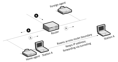
Figure 6. Mobile IP
Range and Throughput
802.11b WLANs communicate using radio waves because these waves penetrate through many indoor structures or can reflect around obstacles. WLAN throughput depends on several factors, including the number of users, microcell range, interference, multipath propagation, standards support, and hardware type. Of course, anything that affects data traffic on the wired portions of the LAN, such as latency and bottlenecks, will also affect the wireless portion.
When it comes to range, more is not always better. For example, if the network requirement is for high performance (5.5 Mbps or 11 Mbps) and complete coverage, long range at lower network speeds (1 Mbps and 2 Mbps) may make it difficult to employ a channel reuse pattern while maintaining high performance.
Mobility
While 802.11b defines how a station associates with APs, it does not define how APs track users as they roam about, either at Layer 2 between two APs on the same subnet, or at Layer 3 when the user crosses a router boundary between subnets.
The first issue is handled by vendor-specific inter-AP protocols, which vary in performance. If the protocol is not efficient, there is a chance of packets being lost as the user roams from access point to access point. Eventually WECA and the IEEE are likely to create standards in this area.
The second issue is handled by Layer 3 roaming mechanisms. The most popular of these is Mobile IP (Figure 6), which is currently known as RFC 2002 in the Internet Engineering Task Force (IETF). Mobile IP works by having an access point assigned as the ?home agent? for each user. Once a wireless station leaves the home area and enters a new area, the new access point queries the station for its home agent. Once it has been located, a packet forwarding is established automatically between the two access points to ensure that the user?s IP address is preserved and that the user can transparently receive his or her data. As Mobile IP is not finalized, vendors may provide their own protocols using similar techniques to ensure that IP traffic follows a user across networks separated by a router (e.g., across multiple buildings).
An incomplete but useful alternative to the Layer 3 roaming problem is to implement the Dynamic Host Configuration Protocol (DHCP) across the network. DHCP allows any users who shut down or suspend their portable computer before crossing to a new network to automatically obtain a new IP address upon resuming or turning on their notebook.
Power Management
End-user wireless products are typically designed to work completely untethered, via battery power. The 802.11b standard incorporates Power Saving Protocol to maximize the battery life of products using wireless devices.
Safety
As with other wireless technologies, WLANs must meet stringent government and industry standards for safety. There have been concerns raised across a number of wireless technology industries regarding the health risks of wireless use. To date, scientific studies have been unable to attribute adverse health effects to WLAN transmissions. In addition, the output power of wireless LAN systems is limited by FCC regulations to under 100 mW, much less than that of a mobile phone, and it is expected that any health effects related to radio transmissions would be correlated to power and physical proximity to the transmitter.
Security
The WEP 40-bit encryption built into 802.11b WLANs should be sufficient for most applications. However, WLAN security needs to be integrated into an overall network security strategy. In particular, a user may implement network layer encryption such as IPSec across both wired and wireless portions of the network, eliminating the need to have 802.11 security in place. Or customers may choose to have critical applications encrypt their own data, thereby ensuring that all network data such as IP and MAC addresses are encrypted along with the data payload.
Other access control techniques are available in addition to the 802.11 WEP authentication technique. For one, there is an identification value called an ESSID programmed into each access point to identify which subnet it is on. This can be used as an authentication check; if a station does not know this value, it is not allowed to associate with the access point. In addition, some vendors provide for a table of MAC addresses in an Access Control List to be included in the access point, restricting access to clients whose MAC addresses are on the list. Clients can thus be explicitly included (or excluded) at will.
Cost
Hardware costs include adding APs to the network infrastructure and WLAN adapter cards to all wireless devices and computers. The number of APs depends on the coverage area, number of users, and types of services needed. The coverage area of each access point extends outward in a radius. Access point ?zones? often overlap to ensure seamless coverage. Clearly, hardware costs will depend on such factors as performance requirements, coverage requirements, and vendor product range at different data rates.
Beyond equipment costs, a customer must take into account installation and maintenance expense, including the costs of poor product quality (help desk support costs, end user productivity). These costs can dwarf the initial equipment costs of a WLAN. Products that are simple to install, use, and manage and that perform up to their specifications may be worth significantly higher initial equipment investment. Features mentioned earlier, such as power over Ethernet, bulk configuration of APs, and a rich set of management tools, will lower the overall cost of a wireless LAN.
Conclusion
802.11 WLANs are already commonly used in several large vertical markets. The 802.11b standard is the first standard to make WLANs usable in the general workplace by providing robust and reliable 11 Mbps performance, five times faster than the original standard. The new standard will also give WLAN customers the freedom to choose flexible, interoperable solutions from multiple vendors, since it has been endorsed by most major networking and personal computer vendors. Broad manufacturer acceptance and certifiable interoperability means users can expect to see affordable, high-speed wireless solutions proliferate throughout the large enterprise, small business, and home markets. This global wireless LAN standard opens exciting new opportunities to expand the potential of network computing.
Acronyms and Abbreviations
AP
access point
BPSK
Binary Phase Shift Keying
BSS
Basic Service Set
CCK
Complementary Code Keying
CRC
cyclic redundancy check
CSMA/CA
Carrier Sense Multiple Access with Collision Avoidance
CSMA/CD
Carrier Sense Multiple Access with Collision Detection
CTS
Clear to Send
DCF
Distribution Coordination Function
DHCP
Dynamic Host Configuration Protocol
DS
distribution system
DSSS
direct sequence spread spectrum
ESS
Extended Service Set
ETSI
European Telecommunications Standards Institute
FCC
Federal Communications Commission (USA)
FHSS Frequency Hopping Spread Spectrum
IBSS
Independent Basic Service Set
IEEE
Institute of Electrical and Electronics Engineers
IETF
Internet Engineering Task Force
IP
Internet Protocol
IPSec
Internet Protocol security
ISA
Integrated Services Architecture
ISM
Industry, Scientific, and Medical
ISO
International Organization for Standardization
LLC
Logical Link Control
MAC
Media Access Control
MIB
management information base
MKK
Radio Equipment Inspection and Certification Institute (Japan)
NIC
network interface card
NOS
network operating system
PCF
Point Coordination Function
PCI
Peripheral Component Interconnect
PRNG
pseudo random number generator
QPSK
Quadrature Phase Shift Keying
RC4
Ron?s Code or Rivest?s Cipher
RTS
Request to Send
SNMP
Simple Network Management Protocol
TCP/IP
Transmission Control Protocol/Internet Protocol
WECA
Wireless Ethernet Compatibility Alliance
WEP
Wired Equivalent Privacy
WLAN
wireless local area network
WLANA
Wireless LAN Alliance
3Com Corporation is publicly traded on Nasdaq under the symbol COMS.
3Com is a member of WLANA, a nonprofit consortium of wireless LAN vendors. To learn more about WLANs and IEEE 802.11, visit their Web site at http://www.wlana.com.
The information contained in this document represents the current view of 3Com Corporation on the issues discussed as of the date of publication. Because 3Com must respond to changing market conditions, this paper should not be interpreted to be a commitment on the part of 3Com, and 3Com cannot guarantee the accuracy of any information presented after the date of publication. This document is for informational purposes only; 3Com makes no warranties, express or implied, in this document. All specifications are subject to change without notice.
转载请注明:在路上 » What is 802.11 & 802.11B ?